
All you have to do is configure the required registers, put your data into the TX FIFO and issue the TX command… and whoa…!! your packet will be in the air, and to receive, configure the radio to be a receiver and when a it gets a packet, it disassembles the packet and makes the data available in RX FIFO. The automatic packet handler in the Nordic radio assembles the preamble, address, packet control field, payload and CRC to make a complete packet before it is transmitted and disassembles it to give the payload after reception of the packet. The radio also features automatic packet handling which features automatic acknowledgement and re-transmission of packets.
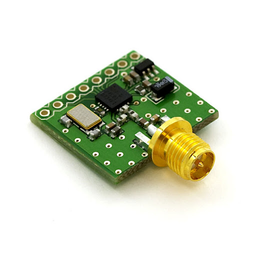
This module uses the 2.4GHz transceiver from Nordic Semiconductor, the nRF24L01+. This transceiver IC operates in the 2.4GHz band and can operate in air data-rates of 250kbps, 1Mbps and 2 Mbps with a maximum power of 0 dBm. The NRF24L01+ IC is a 3.3V device, but its I/O pins are 5 V tolerant , which makes it easier to interface with the standard microcontrollers. The board that Sparkfun designed is having a 3.3 v regulator for power supply, so it is possible to use a common 5 V supply for powering both the micro-controller and RF module.The RF module has an SPI interface and there are about 29 registers inside the radio which can be configured via SPI.

Since I was lazy to write my own library, I choose the RF24 library. MIRF library also works fine, but it provides only a handful of the numerous capabilities of the radio. The sketch was developed step by step, with progress on each step. Initially a one-way remote was developed, which enabled to switch on and off an LED over the wireless link, then a serial port interface was also added, which made it capable to send ASCII strings from a computer. The next step was to create the bidirectional serial data capability, that means the same system should work both as a transmitter and a receiver ( at different instances of time, of course..). The radios were configured normally to be in receiver state when idle and it will wait for any packets on the air. When a packet was detected, it will inform the microcontroller to read it out and spit it into the serial port. The microcontroller waits for data from the serial port, and when a data rrives, toggles the radio into transmit mode, fills the TX FIFO with the data and transmits it. After receiveing the acknowledgement, it changes back to the default receive mode
All the codes are hosted in the github repository.
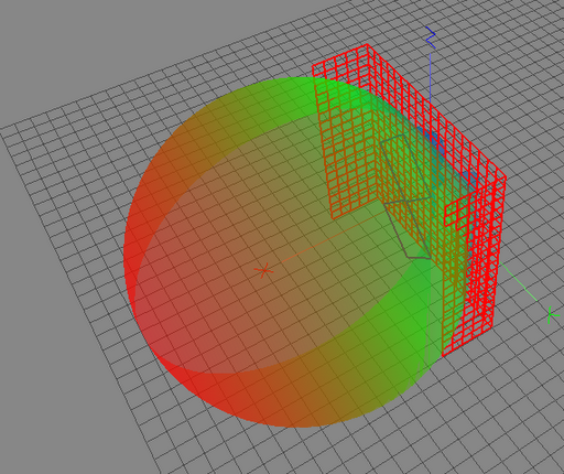
As antennas play a crucial role in deciding the characteristics of a radio system, much care & study was done in choosing them. As the system is intended to be a point to point link, the antenna can be directional and with a high gain. Biquad antenna with reflectors was chosen (thanks to Trevor Marshall) . It is having a good gain of about 10dB and can be made in a couple of hours. The antenna model was made using NEC2 and simulations done. The radiation patterns seemed perfect. The figure below shows a rendering of the 3D radiation pattern of the antenna.
I could not find a mating connector for the reverse polarised connector on the radio module, so the radio had to be mounted right behind the reflector, the antenna directly fed from the connector on the board.. The link worked fine and gave an approx 2 Km line of sight amazing range in the 250 Kbps mode. It was quite wonderful that such a low power device could give such a great distance of link when coupled with a good antenna. The range can be further increased if an antenna with a much more gain is used, like a parabolic reflector antenna ( a parabolic with a biquad feed element would have outstanding performance). Here are a few pictures of the antenna.


The above figure shows the crudely built connector to the feed. The gold colored one is the connector on the Nordic board. A folded aluminium foil was used to connect the signal line of the sub miniature coaxial RF connector to the feed, and a small piece of plastic ( the white thing) was needed to hold the connector tightly.
In the end, I was left with a pair of transcivers operating in half duplex mode which I could plug in directly to the USB port, launch a serial port terminal, and start chatting or send files. 🙂


A really great tutorials , I’ve spent months to find a good article like this 🙂
hi there !! great work . do you have any ideas on how to interface an antenna with the modules that have a pcb trace antenna, because the modules that i have look like this – http://www.elecfreaks.com/wiki/index.php?title=2.4G_Wireless_nRF24L01p
Dimensions on the BiQuad antenna may be calculated here: http://www.changpuak.ch/electronics/bi_quad_antenna_designer.php
Great antennae – Can I have the dimensions please?
why oh why don’t you sell these antennas on ebay. I’ve just wasted over 2hrs unsuccessfully looking everywhere for something like this. Surely I’m not the only other person in the world who wants an antenna like this
Hi,
I’m trying to figure out if this RF link might be the solution for me.
I have a DSLR camera which I connect directly to the computer (simple usb cable) and I’m using it through a software which controls all camera parameters (ISO, shutter, etc.) and gives me a decent live view.
basically I want to cut the usb cable and put a transceiver on each side, just like making a usb cable extension based on RF.
Could this transceiver be the right one for me? If it is, do I need to add any component? if it’s not, is there something else that might give me the solution?
Thanks,
David
This is great stuff on the Nordic RF.. I've wrote a blog entry on linking Arduino & Raspberry Pi using the Nordic NRF24L01+ RF Transceiver. Do head over here if you need to connect between the two popular platform. Setup Arduino and Raspberry Pi using Nordic nrf24l01 rf modules
This comment has been removed by the author.
Great post! I’ve thought about starting my own design blog for years but always had some sort of excuse stopping me. Hopefully the inspiration sticks!
Thanks
Aerial Installations Bognor
Hi I wonder… could you provide measurements and thicknesses? We can't built this without them and who wants to re-invent the wheel. Also have you done any experments with the REALLY cheap radios – same chip – on-board aerial – cutting the pcb aerial and using yours? I'll check in here, I'm also on pete@scargill.org – I'm experimenting with networking these units and being able to add in nodes a kilometre away would be marvelous.
Hello, in my country: Costa Rica (in Central América) is not a crime hacking a WI-FI access point (still). Your antenna may be build in another metal?
Can we have measurements?
@jfvs41 the datasheet for the nRF24L01+ lists the power consumption, it's typically no more than 13mA.
actually here's the breakdown, page 14 of the datasheet:
TX, power amplifier set to 0dBm: 11.3mA
at -6dBm: 9.0mA
at -12dBm: 7.5mA
at -18dBm: 7.0mA
the biggie is probably receive mode, since you spend open-ended periods of time waiting for something:
RX at 250Kbps: 12.6mA
1Mbps: 13.1mA
2Mbps: 13.5mA
PS- Love the antenna mod!
very nice work! 2km range is fantastic! i was wondering if you had any measurements that could give me an idea of the power consumption?