Category: DIY
It was a video about a reconnaissance robot called Recon Scout that inspired me to design a clone of it. Recon scout is a rugged, stealthy and mobile reconaissance robot which can be thrown through a window, over a wall, or down the stairs and it lands ready-to-go. You can even drop it from an unmanned aerial reconnaissance vehicle. Once deployed, you can control its movement at a distance using a hand-held operator control unit.
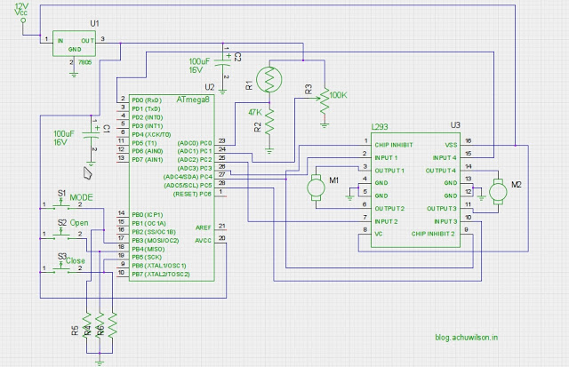
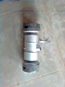
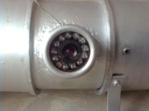
The Recon Scout helps you explore hostile or dangerous environments by providing real-time mission-critical reconnaissance video . My clone is not as rugged as the original Recon Scout and may not withstand extreme conditions, also it is much bigger than the original .The body is built using a PVC pipe and its both ends closed with a PVC cap. Holes are drilled through the cap to mount the motor. The robot is powered using a 12 V, 4.5Ah Lead-Acid battery. The motors are 12V 100 rpm DC geared motors. An additional tail like structure is also provided to enhance stability of the robot while it is moving. The roller robot is also provided with a wireless camera operating in the 2.4GHz ISM band. The camera has a number of Infra Red Leds, which helps much in night vision.The robot is controlled using a custom built RF remote control and the common motor driver H bridge L293D, although any off the shelf RF remote controller can be used.Here are some photos:
Grippers are an important part of robots. Often they are used in gripping and taking objects and play the most important role in robotic arms. Most of the grippers cost much money and may not be easily affordable by hobbyists. Then the best option is to build your own gripper.When it is from the so called ‘useless junk parts’, it becomes more interesting. So let us dive into more details.
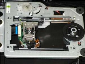
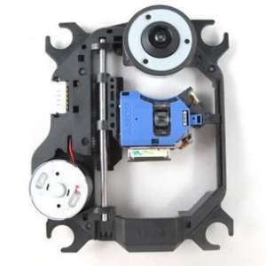
In order to construct this gripper, all you need is the mechanism of on old CD/DVD player, some acrylic sheets or even some small wooden boards for the gripper, some screws and a little hot glue. The mechanism is shown below:
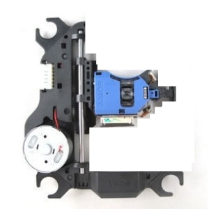
As seen from the above images, the CD/DVD player mechanism consistes of a rack and pinion arrangement to drive the eye across the disc and another stepper motor mechanism to drive the disc. It is driven using a simple DC motor and a pair of gears used to increase torque and decrease the speed of the motor, giving a fine control. Now we can cut and remove some parts of the mechanism, ie, the stepper motor section. Now it will look like this.
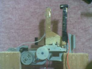
What we are left with is a mechanism shown above. It now consists of only the eye and the rack and pinion mechanism to drive it. Driving the motor causes the eye to move towards and away from the stationary part shown at the bottom of the above picture. Now if we replace the eye with something else (preferably something that looks like a robotic gripper), we end up with a partially functional robotic arm. I think you got the logic behind this, and thats all now use your imagination to work out better… The images of my first working prototype are given below
I also added an Infrared LED and its sensor to the tips of my robotic gripper to detect whether an object is present in between the gripper and it worked pretty nice.


